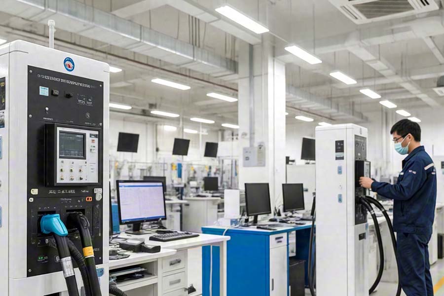
DC electronic load testing of charging pile modules is essential for reliability, safety, and performance. As fast-charging technology moves to 800V platforms (up to 920V) and 480kW power, test accuracy is now a critical requirement for market survival.

For example:
High-voltage insulation safety needs loads to simulate 150% overvoltage conditions, such as 1200V withstand voltage tests. This checks that the protection circuit responds in ≤2ms, meeting the standard GB/T 34657.1 and preventing breakdowns.
Dynamic performance requirements require the load to have a current ramp rate of ≥50A/μs, accurately replicating rapid vehicle acceleration scenarios to prevent output voltage collapse from triggering a BMS interruption (a deviation of ±0.5% can terminate charging).
Core Test Objectives and Corresponding Load Functions

Four Key Test Scenarios for High-Voltage Fast Charging Modules
1. Efficiency MAP plotting across the entire power range
Load operation: Adjust the load current (0-500A) in 10% steps at output voltages between 300V and 1000V.
Value demonstrated:
Locate efficiency dips (e.g., an 800V module's efficiency drops by 3% at 40% load due to SiC driver timing mismatch).
Optimize thermal design by using an infrared thermal imager to locate hotspots greater than 105°C.
2. Wide-range voltage ride-through capability testing
Simulate grid fluctuations: Verify module dynamic response by applying a sudden load increase/reduction (50kW→200kW→50kW):
Constant power mode: 50kW stable for 10s, ramping to 200kW in 0.1s.
Qualification standard: Output voltage fluctuation ≤±5%.
3. Extreme operating reliability verification
Fault injection test: Load simulates an output short circuit (resistance ≤5mΩ); records module protection triggering time (required ≤100μs).
4. Current Sharing Performance of Multiple Parallel Modules
Test Plan: Synchronize multiple loads via the CAN bus, simulating a 500kW power step
Core Indicator: Current imbalance between modules ≤ ±2% (to prevent overload and burnout of a single module)

Technical Redundancies for Load Selection (Taking a 480kW Charging Station as an Example)
1. Voltage Range Coverage: Must support 150V-1000V (compatible with 400V/800V platforms)
2. Transient Response: Current Ramp Rate ≥ 50A/μs (to match the switching speed of the SiC module)
3. Safety Protection Level: Hardware overvoltage protection (OVP) threshold ≥ 1100V; reverse polarity protection (prevents damage to the DUT due to improper operation).
Future Testing Challenges and Load Technology Evolution
Ultra-high Voltage Testing (1500V PV DC Charging Station): The load must support 0-1500V/±1% accuracy.
Realistic Simulation Testing: The load is subjected to a realistic vehicle charging curve (e.g., Tesla V4 Supercharger peak current of 615A).
Conclusion
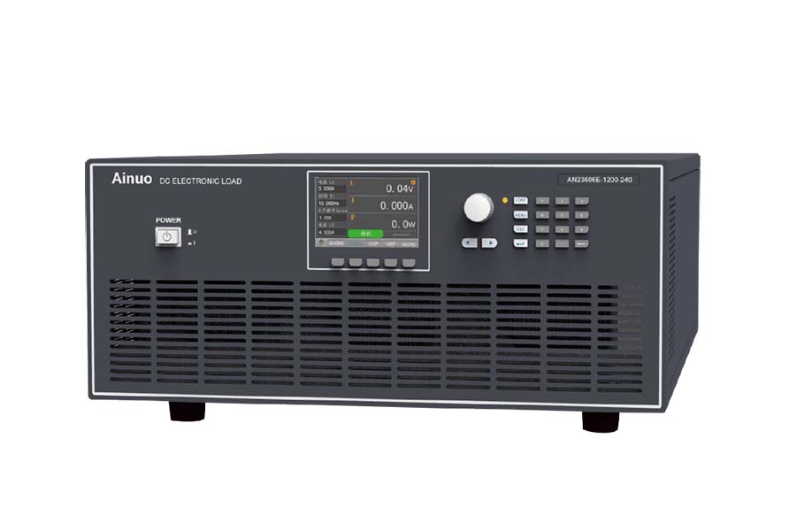
Testing charging pile with a DC electronic load is both a performance mirror and a reliability firewall. Selecting electronic loads with high-precision dynamic response, synchronous control, and high performance (such as the AN23624E series) can accurately expose design flaws and accelerate product iteration. In the fast-charging technology arms race, those who possess more stringent testing capabilities will seize the lead in the 480kW Supercharging era.


